
Links
Contact MeWARNING -- THE AUTHOR TAKES NO RESPONSIBILITY FOR ANY BODY ELSE'S USE OF THE INFORMATION ON THIS WEBSITE! IF YOU DO IT, YOU DO IT AT YOUR OWN RISK! READING THIS PAGES CONFIRMS THAT YOU AGREE TO THIS LEGAL DISCLAIMER -- WARNING
INTRODUCTION
I don't know why, but for years I've played around with how to make digitigrade enhancements for a human (i.e. me). No, I have no clue why I think that, and I don't want to stop being human, and yet I wondered...
Sadly, such dreams remained dreams until I got sick and tired of either having a crappy costume for halloween, or no costume at all. Then I decided to make one. And, being a perfectionist, I wanted to make it as perfect as human possible. And I wanted it unique.
And hence the idea of an anthropomorphic horse costume was born.
It likely would have gone nowhere if a friend hadn't pointed out a Yahoo group dedicated to created hooves for costumes. Most people there create "hoof boots" which are effectively high heels with the heel cut off and a hoof attached to the front sole of the shoe. I'm too much of a perfectionist for that solution, plus reports indicate that it is painful, and possibly hazardous to the human foot.
INITIAL STUDIES
I have seen two designs that were actual digitgrade leg extensions. One used pneumatic pistons for the extra muscles, another used surgical tubing. After much analysis, experimentation, discussion, etc., below are my plans for my own digitigrade leg extensions.
The Force Diagram above depicts the forces acting on the leg with extension attached. The only pivot points that exist for purposes of standing are the ankle joint and the knee joint. Note that the hoof pivots, but the elastic's balance -- the purpose of the pivot is to give additional flexibility to standing, and to give the hoof a "default" position of pointing down to simulate movement whilst walking. Note that "gravitational force" is both gravity pulling the upper leg down, and the ground pushing the leg extension up (as a reaction to gravity pulling the body down).
Note carefully the direction of the arrow pointers!
The key to the whole concept is the elastic "muscle" joining from behind the ankle to the bottom of the thigh.
If you remove the elastic, the force of gravity tends to cause the hoof prosthesis (via ankle pivot) to pivot up and away from the ground (clockwise in the diagram), and the two halves of the human leg to pivot together (via knee pivot) (counter-clockwise in the diagram). In essence, the whole thing attempts to collapse together into three parallel lines perpendicular to the ground -- a stack of sticks.
However, the elastic causes a contractive force between behind the ankle and behind the knee. By pulling together on the other side of the ankle pivot, it causes the hoof prosthesis to want to pivot towards the ground, or in a direction opposite of what gravity wants (counter-clockwise in this case). It is NOT pulling the upper and lower portions of the human leg together (as gravity does) because of the ankle pivot point and the force upward of the ground.
In essence, the leg extension adds a long lever between the ground and the heel of the foot, with the ankle being the fulcrum. As this is much longer than the human foot, the ankle muscle won't support it on its own. Not to mention the issue with standing on tiptoe and damaging the leg tendons. The only "muscle" that needs to be added is between the heel and the upper leg to counteract the increased length of the foot (or the increased link of the lever).
Yes, this is not intuitively obvious. I did not come up with it on my own. The first hoof extension I found online that had detailed documentation initially had a piston for the heel-knee "muscle" and it worked, but balance was extremely hard because the only joint of the extension to the hoof was a hinge. A second piston between the bottom of the human foot and the hoof solved the problem. I had to sit down and force diagram it to see why only the heel-knee "muscle" was needed.
A note on SAFETY: I may be a bit fanatical about doing this, but I am also not stupid (or at least I like to think that). The first thing I acquired for this was a pair of orthopedic knee braces used to brace legs in cases of knee injuries. The idea behind this (thanks again to those who went before me) is to restrict tortional movement in the leg. In other words, to make sure the knee and ankle can't twist perpendicular to the leg bone, and thus breaking important and hard to repair joints. Or, risking a permanently critical injury.
Although the elastic "muscle" between the heel and the knee deals with the issue of the ankle supporting the body's weight, it doesn't deal with the issue of standing on tiptoe for hours on end. This is where the knee brace and the metal shoe support come in. The knee brace consists of a rotational hinge on either side of the knee, foam padding, and three straps that go around the upper leg, and the lower leg (three each). A metal strip goes along each side of the leg joining the rotational hinge. The leg extension is joined to the knee brce at the "Pivot point at ankle". Thus, a portion of the weight of the man is translated to the "Metal Shoe Support" and hence to the hoof and the ground. Some is also translated to the "Metal Shoe Support" by the bottom of the shoe and foot. NO WEIGHT, or very little, is actually supported by the toe of the foot. Instead it is all moved to the ankle (of the 'hoof leg/metal support') and leg.
MODIFICATIONS TO BASE CONCEPT
Due to comments, my current thought is to remove the surgical tubing that links the hoof to the foot, and have a spring, but ONLY at the top/front end of the hoof/foot. Essentially the spring will angle the hoof counter-clockwise in the above picture for a natural appearance whilst walking. Testing will have to be done to see if a single spring works, or if springs on either end are needed. Note that the springs achieve the same mechanical effect, and are simpler to deal with in a small area.
BETA PROTOTYPE/TEST PLATFORM
It has proven difficult to get the metal pieces cut and shaped due to a lack of tools, and a lack of affordable metal. Best quote I've gotten is about $100 for the aluminum for one bracket from an aluminum manufacturer in the US. I haven't had any luck finding other sources. Fortunately, my brother is an automechanic, and can get the sheet steel. He's also building a metal bending machine in his workshop which should be finished in the next few months.
Meanwhile, since Halloween was arriving imminently, I decided to make a simpler prototype to test concepts.
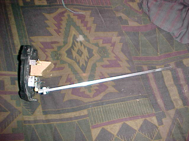
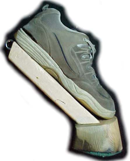 Here we have the basic design,
which consists of three main components. First, an old pair of shoes (the
prototype was done as cheaply as possible, in case it failed miserably).
Second, a 2x4 cut approximately 10" (10.25" long side, 8.25" short side).
Third, a hoof cut out of a 5.25" x 5.25" fence pole. The Hoof is 5.16"
wide at the back, 5" long, 2" high at the back and 2.5" high at the front.
Here we have the basic design,
which consists of three main components. First, an old pair of shoes (the
prototype was done as cheaply as possible, in case it failed miserably).
Second, a 2x4 cut approximately 10" (10.25" long side, 8.25" short side).
Third, a hoof cut out of a 5.25" x 5.25" fence pole. The Hoof is 5.16"
wide at the back, 5" long, 2" high at the back and 2.5" high at the front.
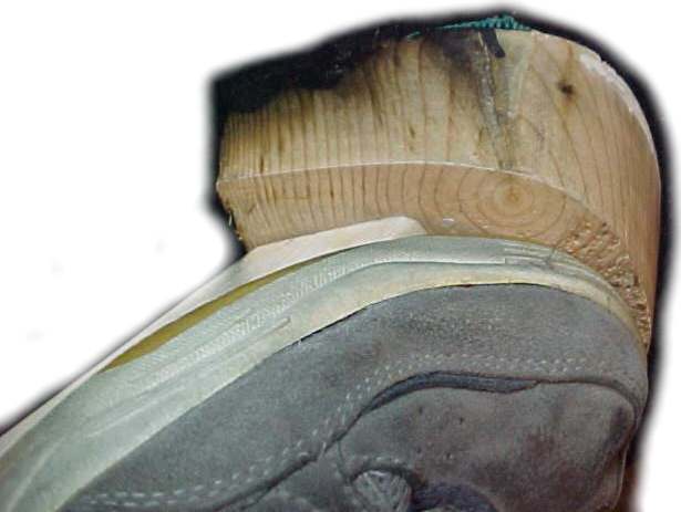
The shoe is an old pair that was retired to indoor work only (painting and such). The 2x4 was simply cut on a table saw. The hoof was cut into a square slab vertically with a chainsaw, and the front half was cut in a half circle on a bandsaw at about a 10 degree angle. The entire hoof was then sanded with a hand sander to make the surfaces roughly smooth.
In other words, this isn't rocket science!
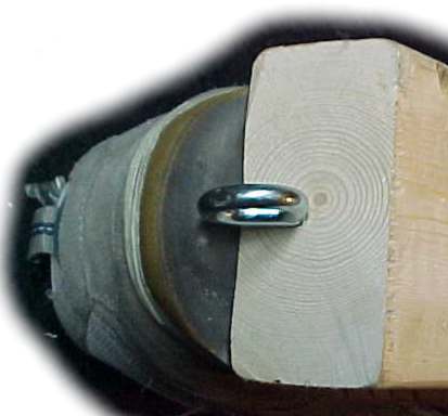
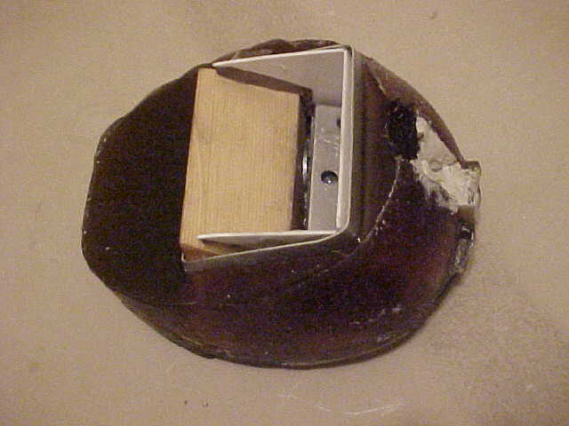
The 2x4 was secured to the hoof in three ways. First, a 0.25" bolt with 0.5" washers at either end, held the two pieces together. A hole for the bolt was drilled beforehand. Secondly, the two pieces were thoroughly glued together with conventional white glue. Finally, to prevent torsional forces from snapping the white glue joint 2 0.25" wooden pegs were glued into holes drilled through the 2x4 and hoof to either side of the bolt.
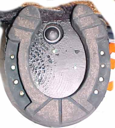
Once the two pieces were thoroughly (and I DO mean thoroughly) secured together, a 1" diameter hook was screwed into a hole drilled at the heel. The hoof was sanded and sealed with numerous layers of white glue, and cracks were sealed with plastic wood. Note that to save costs, the wood was scavanged from my parents fireplace supply. Lots of strength there, and it was free. To complete the hoof, a metal horseshoe gifted from a friend was nailed to the bottom for testing purposes. This picture shows a slightly later enhancement, rubber mesh to keep paper in cupboards from shifting, was wrapped around the hoof and nailed on to provide some traction, and to keep the hoof from scraping up the floor. It's worn in the picture, and due for replacement. Fortunately the stuff is cheap. The human shoe was attached to the 2x4 by a bunch of 1" long drywall screws, about 15 per shoe. Probably a bit excessive, but I'm paranoid about things like this.
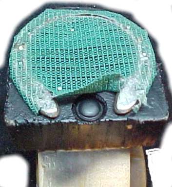
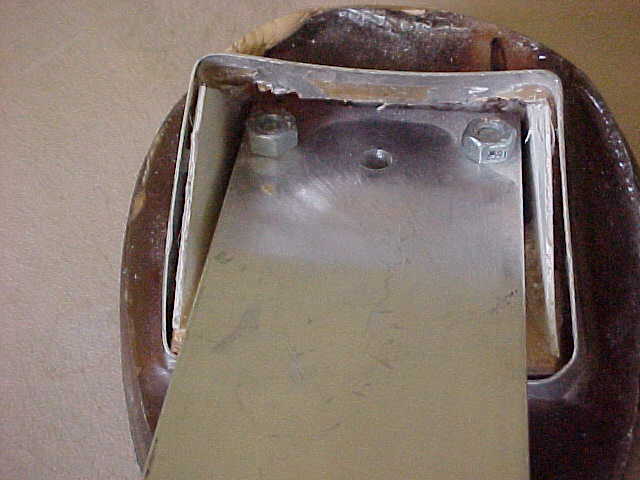
There are some closeups of sections of the hoof. Note that the bottom was sprayed black before horseshoe attachment. Note also a fair amount of plastic wood at the front tip -- I first tried the hooves without the horseshoes, and they chipped very badly, and very rapidly. As a final note, you can clearly see the head of the 0/25" bolt inset to the bottom of the hoof.
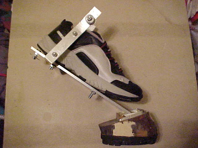
 To
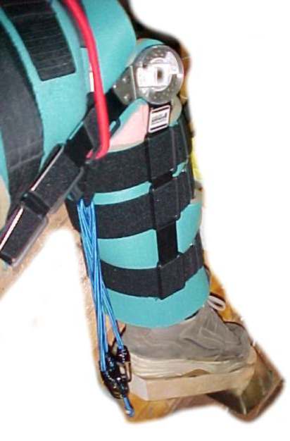
wear the hoof requires two more items. First, a high end knee brace.
Primary purpose is to keep bad things happening to my knee, secondary purpose is
to give some padding to the strap supporting the bungee cords. As I'm
still experimenting with tensions, there is a red bungee cord for additional
strength for the strap that supports the blue bungee cords.
To
wear the hoof requires two more items. First, a high end knee brace.
Primary purpose is to keep bad things happening to my knee, secondary purpose is
to give some padding to the strap supporting the bungee cords. As I'm
still experimenting with tensions, there is a red bungee cord for additional
strength for the strap that supports the blue bungee cords.
The heart of the system are the blue bungee cords. The correct tension appears to be 2 18" cords that are hooked to the hook in the hoof heel, wrapped around the strap, and the other end also hooked to the hoof heal.
Note: I weight ~300 pounds (yes, I need to lose some). Others will likely need less tension. I'm going to try and work out a formula to give others an idea.
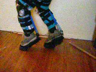
MOTION TESTING THE HOOF
With the bungee cord tension shown here, it is almost trivially easy to walk in them. A couple of times I lost my balance a bit and tried to fall backwards, but the bungee cords kept me from losing it. In earlier walking trials I had only one blue cord, and balance was a constant effort. I could do it, but it took work, and my legs rapidly grew sore. With the two cords, the only real problem was the pressure of the strap on my thigh -- I have some ideas as to how to resolve that.
As to my foot, even with the lower tension, my toes were never sore. Most of my weight is taken by my foot just below my ankle, which is completely surrounded by the snugly tied shoe. The force is spread all around, and so there was never any pain down there.
I'm actually really impressed how easy they are to walk in. Not quite ready to run in them, and will only do so when I'm on some nice soft grass, but I think I actually can right now.
Another impressive result occurred during one early walking test when the thigh strap supporting the (then one) bungee cord came loose; I suddenly lost the heal support and my foot slammed downward so that the 2x4 landed on the floor. No harm was done to me, and no harm was done to the joint between the hoof and the 2x4. In fact, the only harm done to the entire assembly so far has been some chips to the bottom front of the hoof when I tried it without horseshoes. In another "accident" I stepped down on the tip of the hoof, lost my balance, and slammed down onto my knees. Thanks to the knee braces no real harm was done. REMEMBER! SAFETY FIRST!
DESIGN CONCLUSIONS: The design works, can be walked in (with practice) but, it gives me the worst of both worlds. A "hoofboot" type design has a far steeper angle and can be balanced in without the bungee cords; hoof extension designs similar to mine have a shallower angle of the hoof/extension joint. I compromised, and thus have a workable design, but one that could be far comfortable. The second, and far more major issue, is the solid connection between the extension and the hoof. By FAR the hardest part in walking in this set is placing the hoof down flat. Almost always, I put it down on the front or back tip, and then have to adjust my foot angle as I apply weight in the proper direction else I have a sudden catastrophic balance failure. In other words, I fall down.
MATERIAL COST: Wood, free. Bungee cords, screws, plugs, bungee cords, ~$40. Shoes, free. Knee braces, $35 each via eBay ($300 new). Total material cost for Hoof Mk 1 $110.
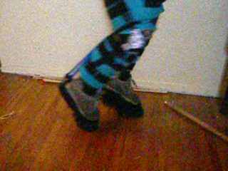
MOTION TESTING VIDEOS: This were taken on a digital still camera that allowed 15s of video. The quality isn't the best, but they give you an idea of the range of motion and how it looks. If you check carefully, you can see how the hoofs step down on a point, and then my leg angle adjusts.
NOTE: Click on the picture to see the video. Videos are in QUICKTIME format.
SMOOTHWALKER RUBBER HORSESHOES: In early January 2007 I finally got a hold of a pair of SMOOTHWALKER horseshoes. These consist of a metal core with a rubber base, commercially available for horses who spent most of their time walking on hard stone/paved surfaces. They work amazingly well, and I highly recommend them. They give amazing traction, and the company was very helpful in finding out what "size" I needed.
BETA 2
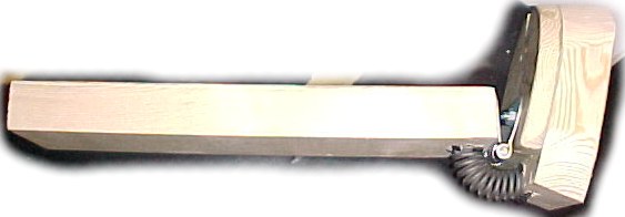
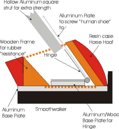
Here is the BETA2 basic concept diagram. Note that it includes the actual methods used in the BETA1, including the use of only a 2x4 for the extension, and the use of bungee cords for the lower leg elastic resistance. The primary change here is the hinge connection between the hoof and the foot extension.
As can be seen by the pivot motion direction, the leg extension will pivot from a right angle connection to the hoof, clockwise (as you view the diagram) until it is parallel to the top angle of the hoof. Obviously, that is too great a motion, so screws are being placed into the bottom of the 2x4 to restrict the maximum angle. Screws are used so that various angles can be tested until the most comfortable one is found. Once that is determined, future designs will build that in. The other change is a compression-resistive spring restraining free motion about the angle in question. Sadly, the spring will push the hoof around clockwise (again as you view the diagram) which will damage the side angle of the hoof in motion. However, from study of the video this should be very minor. Also, this resistance is required given the fact that a human is going to be wearing this.
It seems simple in theory. It turned out to be a right bastard in practice. My first attempt was to cut the base of the 2x4 at a 30 degree angle to provide the minimum angle between the two. In that case there was no way to get the spring on. Then it occurred to me to leave the end of the 2x4 at right angles, use that as the limit on the MAXIMUM angle, and then attack the spring. The first attempt at spring attachment resulted in slicing a hole in the hoof to extend the length -- turned into a disaster. The wood wasn't strong enough. Then I used my backup test cut of "cloven hooves" and get the spring and hinge and 2x4 on.
Looks good, doesn't it?
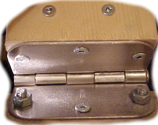
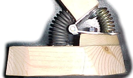
Here is the hinge with spring attached to the back end. Note that the only limit to rotation towards the toe is the bolts holding the hinge on. Bolts were necessary as the spring was so strong there was no way I could pull the hinge down with wood screws. The two wood screws you can see in the 2x4 are reinforcement screws to keep the wood from splitting (which happened with an earlier attempt when I unknowingly had the hinge on backwards so that I was trying to force it to close beyond what it was physically capable of.
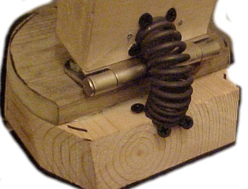
And here is the rear spring. Yes, the connection method is crude, but remember that this is a test model, and I expected to fiddle a lot with it. I was right as it turned out. You can also see the default/rest angle of the hoof/2x4 here -- almost vertical.
BETA2a TEST
They were unusable. The angle was so steep that I could not walk. My feet had to be vertical to use them, and I just could not do it. I had to try to walk steep to get any kind of safe contact with the floor, even with the flexibility. If I walked normally, I was balanced on the bottom corner, and the hoof tipped backward.
After a lot of thought, I concluded that the problem was the default/rest angle of the hoof. To change that I inserted another spring within the hinge in a fairly crude fashion. It did change the default angle, but it also made the spring resistance to movement between the hoof/2x4 VERY stiff.
Above you can see the default angle of the hoof. Note the Smoothwalker has been SCREWED to the bottom -- the holes in the metal centre were wide enough for screws which will make removal for painting/finishing, and transferring to the final hoof, VERY easy. YAY Smoothwalkers!
Sadly, although I could now stand on them, the combination of the two springs was SO stiff, that the hoof would not move at all with the weight I put on it. Note that the pivot point is almost right at the back, so there is very little force at the front to press the hoof flat.
BETA2c
The next question was whether to change the spring tensions to change the default position, and make the movement easier, AND/OR move the hinge further forward to change the location of the forces. I decided to try "softer" springs first, as that would require a lot less work, and work that would not commit me to a different position of the hinge.
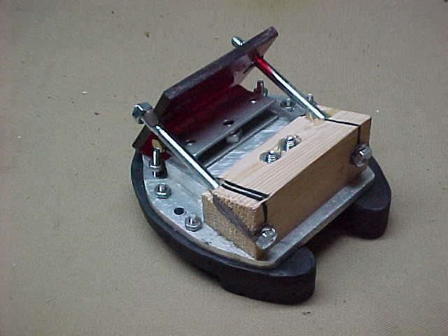
It occurred to me that the non-cloven hooves that had been hacked up at the back were perfectly usable for the "reposition hinge" test. So I ended up doing that first. Above you can see a completed BETA2c ready for trials.
And yes, they actually WORK! WOOHOO!
Walking is a LOT harder -- the feel... soft. I'm so used to the BETA1s, which had no movement between the 2x4 and the hoof, that being able to move up and down feels very strange. The balance required is also VERY different -- it took me a bit to get the hang of it. But, once I did, I felt much more stable on my hoofs. Sadly, there was a minor structural failure in the first test -- the joint between the front spring and the hoof failed. In essence, the washer I had handy was too large and the spring "wiggled" loose. No harm was done, nothing was broken. I never even noticed it till I took them off.
BETA2d and BETA2e
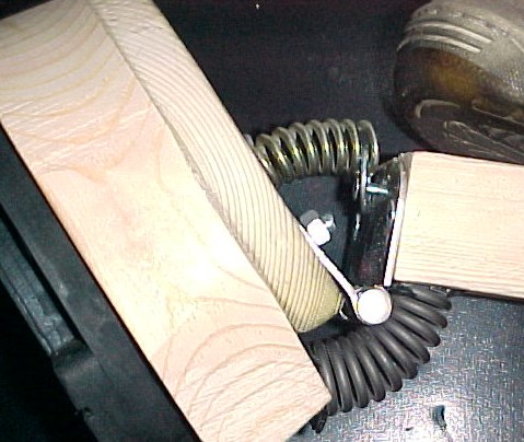
Further testing revealed that the angle was too steep. I could walk, abut the heel of the hoof came down first, and it didn't sound good. So, I replaced the front spring with a stronger spring, and that fixed that. With this model I could almost hear a "clomp" sound, but I think the interior floor is too soft.
Sadly though, the forces involved were great enough that the screws holding the hinge to the 2x4 would slowly be pulled outward. 300 steps, and the 3" long screws were pulled out by about 5mm. It was even worse with the left hoof as the 2x4 had cracked as it was from the BETA2a test before I had reinforced the 2x4 with two screws put in perpendicular to the hinge screws (the crack was from when the hinge was attached backward and I was trying to bend it further than the hinge would go). So, I replaced that 2x4 entirely with a spare (Home Depot gives three free cuts with a purchase, and I saw no reason not to use the third!) and then attached the two screws on the hinge on the 2x4 with significantly huge gobs of five minute epoxy.
The 300 step test of the glued model confirmed that there was no screw movement and the system was stable.
CRITICAL SAFETY INFORMATION
A number of people have (strongly) suggested that I should run a small chain down the centre of each spring to prevent flying pieces of shrapnel if a spring snaps. It had never occurred to me, but I MUST *MUST* agree with them. Because of the way I'm holding the springs on a chain isn't going to do it, but I am going to run a ~1mm thick strand of twisted metal through them. This will be the BETA2f.
If you go with springs *USE SOMETHING TO PREVENT DISASTER!*
BETA 2f:
I ended up using coat hanger wire as it was handy, and I could get it through the required holes. Now, for a deadly shard of spring to go flying through the air, the spring has to snap in TWO places (since it's secured at both ends), and the coat hanger wire has to either snap at one place, OR the coat hanger wire has to be pulled out at least 3", and bent he entire length.
They should be safe now.
INITIAL OBSERVATIONS:
I've walked over a thousand steps in them now, so I have some more concrete observations.
They're fairly easy, once you get used to the balance. I still take the first couple of steps leaning onto the wall, or a shelf unit, to regain the "feel" of them. However, once I've got that back, they are FAR easier to walk in than the BETA1s. Not to mention far more stable. I can fairly easier do 300 steps at a time, and it took me hours of practice to get to that stage with the BETA1s. I now feel confident that I can reach the point where I can walk around all day in them. As expected, the balance is INCREDIBLY better. Between my room and the next one, there is a door way with a lip in the floor you have to step over. With the BETA1s I learned to avoid it at all costs as it was incredibly hard to balance on. With the BETA2s I can easily step on it, and don't even notice any balance difference. The hinge ensures the hoof has full floor contact, and allows the foot/ankle to move a bit to adjust my balance.
Note that there is a problem/oddity with the hinges: one is fine, but the other, the left one, the pin slowly works its way out. I have to keep an eye on it and hammer it back, but, still... Looking at the hooves side by side, the left shoe was not perpendicular to the floor. Adjusting that may or may not help with the hinge pin.
Sadly, I have to conclude that springs are a dead end design. They are mechanically complex, finicky, and nearly impossible to assemble unless I can figure out a way to vary their tension. I either need to assemble a complex mechanical adjustment that I can use to shorten/lengthen the area the spring is in, or find some kind of spring that can be adjusted. Spring-loaded gate hinges MIGHT work, but I don't think they're strong enough.
In essence, it requires my entire strength, a vice, pries and hammers, spit and prayer, to get the front spring in. And, it doesn't go where I want it, it goes where I can get it to. This is not good for an elegant design.
BETA 2g (does it ever end?!):
This is the final version of the spring loaded hoof version. Essentially, I picked up aluminum fence construction bits and was able to bind the knee brace to the hooves, with a pivot point at my ankle. Or, as close as I could get. It's ugly, it's crude, but it tests the concept and the mechanics.
FINAL OBSERVATIONS OF BETA2 SERIES:
I learned a lot from the BETA2 series. Most of it boils down to how useful it is for the hoof/shoe holder pivot joint to be able to pivot, along with the need to get the pivot point as far forward as possible. The rest, just added now though originally planned, was how useful it is to bind the knee brace to the actual hoof. It makes the whole thing much more stable.
What it also proved is that I had the basic mechanics down, I just needed a better and safer execution/presentation methodology.
BETA 3
The BETA3 should be the final design. Mechanically it is similar to the BETA2 series, BUT there are no springs and no hinge. Instead the hoof is cut into a hollow shell, and the 2x4 is connected with a pivot bar/screw so that it can freely move inside the hollow space in the centre of the hoof. The key to making the system work is that the 2x4 is suspended in the neutral position, and then Casting Rubber is poured into the empty space (appropriately dammed) and allowed to harden. This rubber will serve as the dampening material for the movement. It is still not adjustable once poured, but different rubbers can be selected, and the default angle of the 2x4 and hoof can easily be set up. It is also FAR simpler mechanically, having only the pivot point screw to worry about.
Early development did change some things, mostly changing almost all the construction to aluminum as compared to wood. Given that it all had to hide inside a realistic looking hoof shell, size suddenly became important, and that forced the originally planned conversion to aluminum to be incorporated with this series.
BETA3 BASIC DESIGN CONCEPT:
Above is the original concept for the BETA3 model. The originally plan was WAY over engineered, including a base plate, and an aluminum hollow bar to keep the human shoe holder from bending. The rest remained relatively unchanged in idea, though execution modified it.
BETA3 HOOF MASTER:
The basic procedural plan was to sculpt a master hoof out of clay or a similar material, make a mold of it, and then cast the final hoof around the aluminum/wood framework. Logically, the hoof shell was needed first. Studies of pictures and dimensions of actual hooves, along with the Smoothwalker shoe, led to the master shown below. Although not shown, the bottom was also detailed. Note that the bottom was actually almost a centimeter below the top of the horse shoe. Although unrealistic, it would be visually correct, the error only apparent from certain angles, and when one started comparing dimensions. The extra thickness was required so that the bottom design was below the internal framework, and was thick enough to make sure it wouldn't break easily.
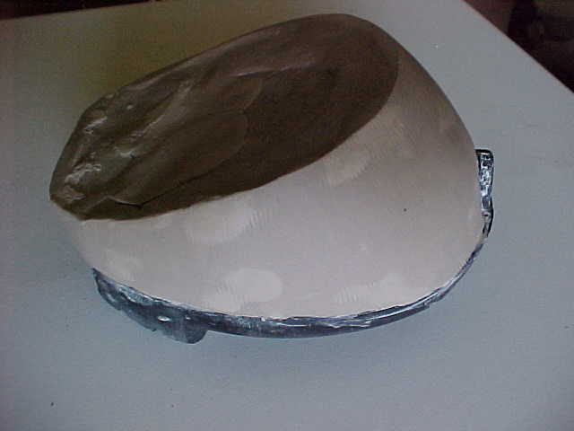
Sadly, this hoof sculpt was probably the biggest mistake of any of the hoof designs. The reason is quite simple. Although fairly anatomically correct, it did NOT take into account the physical dimensions of the mechanisms required to make the hoof stilts work. If the mechanism doesn't fit inside the sculpted hoof shell, then the entire project is a failure. Once the hoof was sculpted and molded, almost every construction step was driven by the need to make the mechanism as tiny as possible to fit within the available hoof shell.
IF I had constructed the internal mechanism first, and then sculpted a shell that would fit around it, as close to anatomically correct as I could get whilst still allowing sufficient room for the mechanism, life would have been FAR easier. Instead most of the interior construction was driven by the need to be SMALL rather than any mechanical/physical constraints.
CRITICAL SAFETY TIP: Build the interior first, and then sculpt the exterior to fit around it!!
BETA3A INTERNAL MECHANISM:
Here was the 3A shell design. It was mounted on a 1/4" aluminum plate roughly cut to shape (an afternoon's job - GAH!). The hinge was mounted on a 1"x4"x1/2" aluminum bar. The wide was because I originally planned to use larger hinges until I discovered the tiny space I had to work in. I was going to use another 1/2" bar to support the wood to support the lower limit of the shoe arm movement, but testing showed that the 1/4" plate was more than strong enough. As significant pressure would be caused whilst I was stepping forward (leaning forward with the hoof) I created an extra strong forward wall that was held to the wooden back frame by 1/4" bolts for even MORE strength.
Then an e-mail chat online brought up weight issues, along with the excessive over engineering. And, I realized that there was no WAY that would ever fit inside the hoof shell.
BETA3B INTERNAL MECHANISM:
The driving forces behind the 3B were decreasing the weight, and decreasing the size. The width of the shoe support was reduced to match the hinge. The bottom plate was completely removed. The bar supporting the hinge was reduced to match the width of the hinge. A small square bar was added to the back of the wooden block to provide extra support for it A 1/4" bolt joined the bar to the wooden block to the square bar to keep everything neat and lined up.
Above you can see the BETA3B prior to adding the shell walls and front. The revised plan for the 3B counted on the innate strength of the resin to surround the rubber. Thus, the only kind of wall needed was one to keep the resin out whilst it was poured to shape the hoof. The rubber could then be poured into the existing cavity and all would be good. The final shell was made of 1/32" plastic sheet in three pieces. Two sides and one front. The bottom would be formed by making two resin pours -- one to just above the level of the shell, and the second to fill the rest. The bottom pour would dry first, sealing in the shell for the rubber.
Before final pouring, fear of strength resulted in a 1/32nd x 1" strip to wrap around the top of the plastic shell, and be screwed to the back of the block of wood. This way for the resin front of the hoof to break, the aluminum strip would have to be broken first.
Of course, it turned out that this mechanism was WAY too big--
INTERNAL MECHANISM NOTE:
In all cases in the construction of the internal mechanism, all components were epoxied together; all bolts were epoxied into their holes, and the nuts epoxied onto their ends. This maybe was a bit paranoid, but once the resin was poured, and/or the rubber, there was NO access. If something worked lose, there would be no visual indication, and no way to fix it.
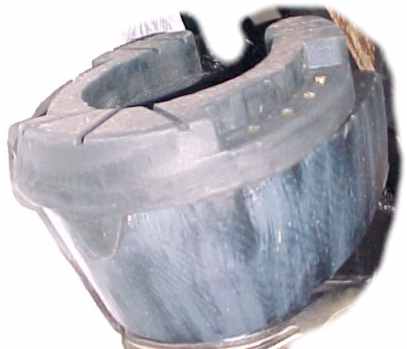
BETA3B RESIN SHELL:
Below is the raw pour of the resin shell. You can see the plastic wall, and the top of the aluminum strip added at the last minute.
You can also see the horribly deformed crack/split at the front filled with a white clayish material.
As I put the first shell and Smoothwalker in the mold, I discovered, to my horror, that the shell for the rubber was FAR too big. After a bit of good old fashioned panic, I cut the front of the mold open, put in an old scrap for a spacer, filled the resulting wedge with clay, and sealed the crap out of the mold with Duct Tape. I prayed a lot, and then poured the bottom section, and then the top.
The heat of the resin curing softened the clay so that it melted, pushing the resin out of the way leaving the gouge shown above. The clay is the clay. However, the Duct Tape kept the resin from leaking out, which made this last minute panic solution at least doable!
The resin body was finished by cleaning the clay out, and then filling the gaps and chips (there were some issues with removing the Smoothwalker from the bottom) with plastic wood.
But, at least it looked like a hoof!
INTERNAL MECHANISM DETAILS:
Below is a close up of the internal mechanism just prior to pouring in the rubber.
This was the greatest nightmare of them all. With the shell, the hinge and shoe support had close to a 90 degree range of motion. After the shell, and before any modification, the shoe support had about 5 degrees of motion. To improve this I did two things.
First, I chiseled and pried and yanked and drilled and otherwise got out the front plastic piece the created the shell. It was no longer needed as the resin was dried and it would provide the shell to enclose the rubber. It allowed room for the aluminum shoe support to rotate. Second, I drilled holes so that the nuts could move further forward (you can see the chewed up edge of the aluminum strip above each bolt). This would allow the bolt to move slightly further forward, providing even more direction. Third, I didn't use the third hole in the hinge. As most stress would be pushing the back of the shoe support down, all the force would be on the two forward hinges. Removing the third hinge removed the need to drill a third hole, and allowed even more motion.
As a result of hacking and chiseling and drilling, I got the motion up to just under 40 degrees.
POURING THE RUBBER:
A simple step actually. The shoe support was set at the desired angle (held in that position by large external clamps), and the rubber was poured in. Then wait to dry.
BETA3B FINAL PROTOTYPE:
After two days of waiting, and worrying, the clamps were removed. Using pre-drilled holes, a human shoe was bolted to the support, a U-shaped strip of aluminum was screwed on to act as a mount for the knee brace, and a bolt, nuts, and a washer were used to provide a hook for the bungee cords. Note that I went with the hacked together bolt/screws/washer as I could find no hook that I could screw to the aluminum shoe support.
The entire mechanism below, as shown, weighs just under 5 pounds. I may drill out some of the back of the resin hoof as it isn't needed, and the resin (a stronger fibreglass resin) was heavier than what I normally used. Should be able to save about half a pound that way.
BETA3B FIRST TEST:
With mounting terror, I tied on the shoes and strapped on the knee braces (not shown above). They actually worked.
It had been a while since I tried the BETA2 model, or even the BETA1. They were certainly a lot less "soft" than the BETA2. They also seemed easier to use than the BETA1. Unfortunately, it seems that the rubber is too stiff. Although there had to be some give, I found that when standing still, one hoof would often not be flat on the floor, indicating the rubber was too stiff to allow the human shoe support to move.
Still, they worked!
BETA3C:
In an attempt to destiffen the rubber, I drilled two small holes both in front, and behind, the shoe support. This would allow the rubber some easier flex. I also pulled the front loose from the shoe support. It was still there, just not "stuck" to it. Another resistance to movement no longer present.